Machining Stainless Vacuum Flanges: ICF, NW and JIS Flange Parts Compared
Process / 17 Oct 2026
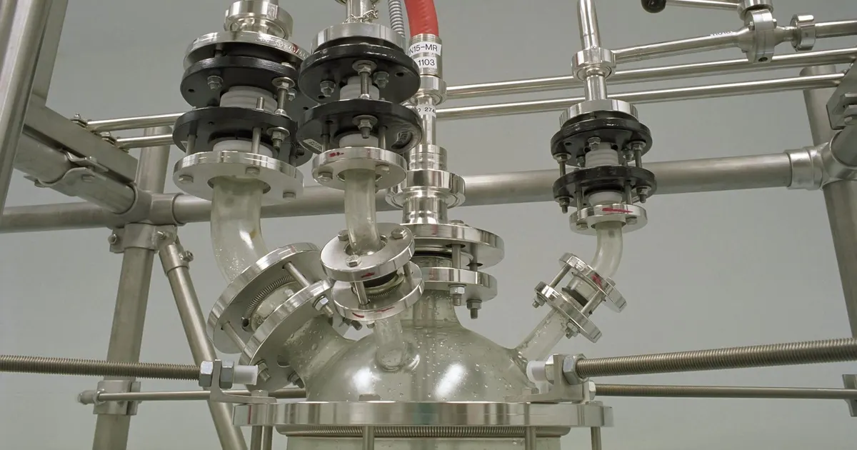
A vacuum flange is a simple shape: a disc with a bore, a ring of bolt holes and a sealing face. It is also one of the least forgiving parts a machine shop makes. A scratch of a few micrometres across a sealing face is a leak. A dull knife edge cannot bite into its gasket. A blind tapped hole in the wrong place keeps a pocket of air that the pump takes hours to clear. The drawing for one is usually short, and the work is in what the drawing assumes the shop knows.
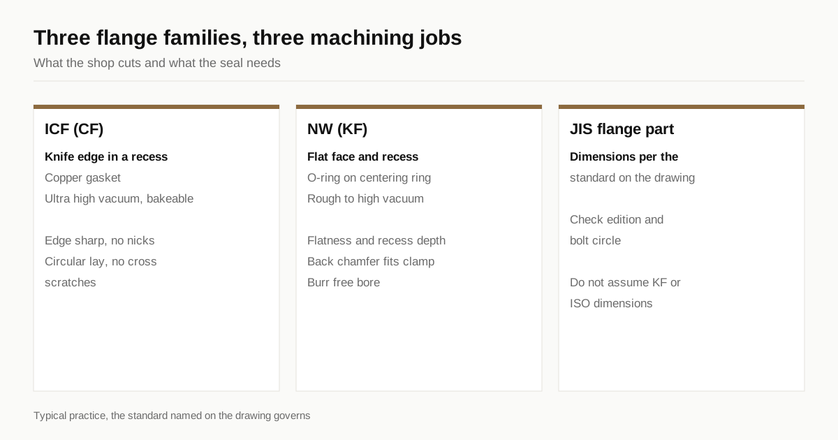
This guide covers the three flange families that come up on drawings from Japanese buyers, ICF, NW and JIS flange parts, and what machining them requires.
The three families
ICF (CF, ConFlat). A metal sealed flange for ultra high vacuum. Each flange face carries a sharp circular knife edge in a shallow recess. Two flanges are bolted together with a flat copper gasket between them, and the knife edges cut into the copper to make a seal. ICF flanges are bakeable to several hundred degrees C and used where pressure drops far below the range of rubber seals.
NW (KF). A quick connect flange for rough and high vacuum. The flange has a sloped back face and a flat sealing face with a shallow recess. A centering ring with an O-ring sits between two flanges, and a clamp pulls them together. The NW number is the nominal bore size in millimetres: NW10, NW16, NW25, NW40, NW50.
JIS flange parts. Japanese drawings may cite a Japanese vacuum flange standard for dimensions. JIS B 2290 is the one that is commonly named, but the drawing, not the shop, should state which standard and edition apply. Flanges built to a JIS drawing can follow dimensions that are close to the international KF and ISO families and differ in details such as bolt circle or clamp angle, so a drawing should not be read as another family without checking.
| Family | Seal | Typical vacuum range | Bakeable | Typical use |
|---|---|---|---|---|
| ICF (CF) | Metal knife edge into copper gasket | Down to ultra high vacuum | Yes, to several hundred degrees C | Chambers, analysis tools, UHV lines |
| NW (KF) | Elastomer O-ring on a centering ring | Rough to high vacuum | Limited by the O-ring | Roughing lines, pump connections |
| Larger ISO flanges | Elastomer O-ring, bolted or clamped | Rough to high vacuum | Limited by the O-ring | Large ports, pumps |
Ranges are typical and the application and the seal choice govern.
Machining a knife edge
The knife edge is the critical feature on an ICF flange. It is a thin ridge that has to cut into a copper gasket and stay intact through repeated use. Its shape, sharpness and surface decide whether the flange seals.
Geometry. The drawing or flange standard gives the knife edge angle, the height and the recess dimensions. The tool that cuts it is ground to match, and a worn tool leaves a rounded edge that will not seal. Shops that cut knife edges inspect the profile on an optical comparator or a measuring microscope.
Burr and damage. The edge must be free of burrs and nicks. A single nick in a sharp edge is a leak path, and a loose burr falls into the gasket. After cutting, the flange is protected, usually with a plastic cap or a recessed fixture, and not allowed to touch other parts.
Surface finish. The faces around the knife edge are finished fine, and no scratch should cross the edge. Lay direction should be circular.
Hardness and material. Stainless is chosen so the edge is harder than the copper gasket. Austenitic grades such as SUS304L and SUS316L are normal, with grade chosen on the drawing. A sharp tool is needed to cut a clean edge, and the edge is checked before the flange is cleaned and packed.
Machining NW and ISO faces
NW and ISO sealing faces are simpler in geometry and just as sensitive to finish.
- The sealing face is flat with a shallow recess for the centering ring. Flatness, finish and the recess depth set how the O-ring is squeezed.
- The back chamfer matches the clamp, and the angle and diameter need to be held so the clamp seats.
- The bore has to be clean and burr free, with a controlled chamfer at the entrance.
- Finish. A fine turned finish with a circular lay is normal. Cross scratches are not acceptable.
For both families the surface finish guide explains the Ra and Rz notation, and the burr free guide covers the wording for edges.
Bolts, threads and galling
Flange bolts are a small detail with a big effect. Stainless bolts in stainless tapped holes gall, and a seized bolt on a baked ICF flange is a familiar problem. Vacuum suppliers handle it with silver plated or coated bolts and nuts, or a dry film lubricant approved for vacuum, and with threads cut to a class that leaves clearance. Ordinary oil or grease is not allowed in a vacuum space.
For the machine shop, three points follow. Tapped holes in the flange need clean, burr free threads, because a burr is both a particle and a seizing point. Thread class and depth should be given on the drawing, with the thread callout guide as the reference for wording. And the holes should be through holes wherever the design allows, so the thread does not trap gas.
On ICF flanges the bolt holes are normally clearance holes with a nut on the far side. Tapped holes appear on one flange of some pairs to allow assembly in tight spaces, and those are the ones that need vented bolts.
A worked example
Take a CF flange blank for a viewport adapter in SUS316L. The drawing gives the outer diameter, eight clearance holes on a bolt circle, a central bore, a knife edge recess on one face and a tube weld prep on the other.
A sensible route cuts the flange from forged or bar stock in one chucking where possible, so the bore, the knife edge and the outer diameter stay concentric. The knife edge is cut last with a ground tool and inspected at 20 times magnification. The bolt holes are drilled and deburred on both sides. The weld prep is cut to the drawing angle. The part is washed, protected with a cap on the knife edge and bagged.
The inspection report gives the outer diameter, bore, bolt circle, recess depth and knife edge profile result. A reader who sees only “flange: OK” has nothing to compare against the drawing. The seisekisho guide lists the fields a good report holds.
Leak paths a drawing should prevent
Blind tapped holes. A blind tapped hole on the vacuum side traps gas. A through hole, a vented screw or a vent drilled across the thread avoids it. Bolt holes on a flange are normally through holes for this reason.
Porosity. Bar material for vacuum parts should be sound, and some buyers specify forged blanks or vacuum remelted material for critical flanges. If the drawing names it, the shop must supply it, and the mill sheet shows it.
Welds. Flanges are welded to tubes and the weld prep matters. A butt weld prep or a tube stub is cut to a defined bevel, and the part must be clean. A weld in a vacuum space needs full penetration and no trapped crevices. The prep is the machine shop’s part and the weld is the next step.
Trapped volumes. Any closed pocket in a vacuum space holds gas. Parts should drain and vent.
Tolerances that matter
Most flange dimensions come from the standard and tolerances are tight where they affect sealing.
| Feature | Typical tolerance | Why it matters |
|---|---|---|
| Sealing face flatness | 0.02 to 0.05 mm | Seal uniformity |
| Recess depth | 0.05 mm or per standard | O-ring squeeze or knife edge engagement |
| Bolt circle position | 0.1 mm | Alignment with the mating flange |
| Bore concentricity to flange | 0.05 mm | Alignment of tube and flange |
| Knife edge profile | Per standard | Seal |
These are common working values and the standard governs. The geometric tolerance guide explains how flatness and concentricity are read, and the general tolerance guide covers features without their own limits.
Cleaning and packing
Vacuum flanges need clean surfaces. The route is the same as for other vacuum parts: remove cutting fluid, ultrasonic wash, rinse, dry and bag, as in the semiconductor parts guide. Sealing faces are covered with protective caps or film so they are not scratched in transit. Parts are packed individually. A flange that arrives with a scratched face goes back.
If the buyer needs passivation or electropolishing, state it and the order of steps. A sealing face that is electropolished loses some material, and the drawing should allow for it.
Leak testing
Helium leak testing checks the flange after it is welded into an assembly, and sometimes on the bare part with a test fixture. The test needs equipment, a fixture and an agreed limit. It is not part of machining. If the buyer needs a result, it goes onto the order with the method and the limit, and the test is arranged and recorded separately.
What to put on the drawing
- The flange family and standard with edition.
- Material and condition, such as SUS316L solution treated.
- Sealing face finish and lay.
- Knife edge or recess dimensions from the standard.
- Venting for any blind hole in the vacuum space.
- Cleaning and packing instructions.
- Inspection items: flatness, recess depth, knife edge profile.
Checklist
- Is it ICF, NW or a JIS flange? Check the standard on the drawing.
- Are sealing face finish and lay given?
- Is every hole through or vented?
- Is the cleaning and packing route named?
- Is leak testing wanted, and if so, with what limit?
To price a flange part, send the drawing. An engineer reads the standard, the finish and the venting notes, flags any that need a decision and quotes within 24 business hours. The engineer follows the order and signs off the inspection before packing, and the capabilities page lists the processes and tolerances we quote.
Questions
What is the difference between ICF and NW flanges?
ICF, also called CF or ConFlat, seals metal to metal with a knife edge cutting into a copper gasket and is used for ultra high vacuum. NW, also called KF, seals with a rubber O-ring on a centering ring held by a clamp and is used for rough and high vacuum.
Do flange sealing faces need a special surface finish?
Yes. The sealing faces and the knife edge or groove must be free of scratches that cross the seal. Finish and lay direction are stated on the drawing or in the flange standard.
Is helium leak testing part of machining?
No. It is a separate test. If the buyer needs a leak rate on the finished part, it has to be named on the order with the method and the limit, and the test arranged.
Have a drawing for a stainless part?
Send it and an engineer reads the title block, quotes it within 24 business hours, and if you order we place, manage, inspect and ship the parts on one PO and one invoice.
Get a quoteRelated guides
SUS303Se and SUS303Cu Compared with SUS303: Which Free Cutting Grade to Use
SUS303Se and SUS303Cu against standard SUS303: what selenium and copper change for finish, cold forming and corrosion, and what a drawing should state.
SUS Spacers and Collars to JIS Drawings: What Drives the Price of Small Lots
How stainless spacers and collars are made from JIS drawings in small lots: length and parallelism, bore and set screw details, stack-up and price breaks.