JIS B 0021 Geometric Tolerances on Stainless Parts: How to Read the Frames
Drawings / 13 Oct 2026
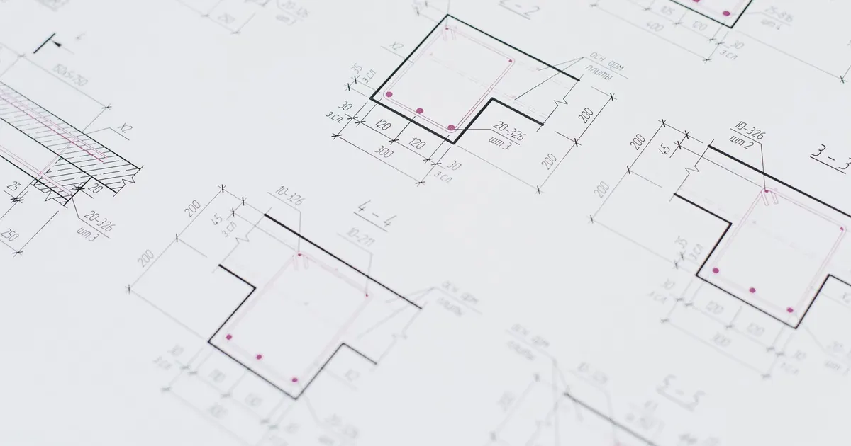
A frame like a small box with a symbol, a number and two letters is the part of a Japanese drawing that cost estimators most often skim. It should not be skimmed. The frame tells a shop which feature to measure, how it is measured and what the zone looks like. A diameter tolerance says how big a feature is. A geometric tolerance says how well it is shaped and where it sits. Both decide whether a stainless part passes inspection.
JIS B 0021 is the Japanese standard for geometrical tolerancing and it follows the same system as ISO 1101. If you can read one you can read the other. This guide covers the frame, the fourteen symbols and what each means to the people holding the gauge.
The frame, read left to right
Every geometric tolerance sits in a rectangular frame divided into cells. Read the cells in order:
- The symbol. What kind of control this is: flatness, position, runout and so on.
- The tolerance value. The width of the zone in millimetres. A diameter sign in front of the number means the zone is a cylinder, not a flat band.
- The datum letters. One, two or three capital letters that name the reference features the measurement starts from. Form controls such as flatness have none because they refer to the feature itself.
A letter in a filled or open triangle on the drawing marks the datum feature. A thin leader line with an arrowhead joins the frame to the toleranced feature. If the arrow lands on the dimension line, the control applies to the axis or centre plane. If it lands on the outline of the surface, it applies to the surface.
That last distinction is where misreads start. An arrow on the outline controls the surface. An arrow in line with the dimension controls the axis. The same number has a different meaning on each.
One frame, read in full
Take a frame that holds a position symbol, then a diameter sign, 0.1, then the letters A and B. Read it as: the axis of this feature must lie inside a cylindrical zone 0.1 mm across, and that zone is located from datum A first and datum B second. The order of the letters matters. Datum A is the primary reference, usually the face the part sits on. Datum B is the secondary reference, usually a bore or an edge. A shop that picks the part up on B first and A second measures a different part from the one the designer drew.
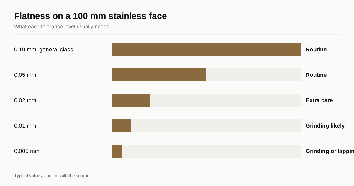
A frame with only a symbol and a number, such as flatness 0.05, needs no letters at all. The zone is two parallel planes 0.05 mm apart and the whole surface has to sit between them, whatever angle the part is held at.
The fourteen symbols
The standard groups the symbols by what they control. Datum-free form controls come first, then orientation, location and runout.
| Group | Symbol name | Controls | Datum needed |
|---|---|---|---|
| Form | Straightness | A line element or an axis | No |
| Form | Flatness | A surface | No |
| Form | Circularity | A cross section of a round feature | No |
| Form | Cylindricity | A whole cylindrical surface | No |
| Form or profile | Profile of a line | A section outline | Optional |
| Form or profile | Profile of a surface | A surface outline | Optional |
| Orientation | Parallelism | Angle to a datum, 0 degrees | Yes |
| Orientation | Perpendicularity | Angle to a datum, 90 degrees | Yes |
| Orientation | Angularity | Any other fixed angle | Yes |
| Location | Position | Location of a feature | Yes |
| Location | Concentricity or coaxiality | Axis against a datum axis | Yes |
| Location | Symmetry | Centre plane against a datum | Yes |
| Runout | Circular runout | One cross section while the part turns | Yes |
| Runout | Total runout | The whole surface while the part turns | Yes |
Concentricity and coaxiality share a line in the table because many drawings use the concentricity symbol where the intent is coaxiality of an axis. Ask which one is meant when it matters, since the measurement method differs.
What each group costs on a stainless part
Austenitic stainless does not hold its shape the way carbon steel does. It has a low thermal conductivity, it work hardens and it relaxes when the outer skin is removed. Each of those shows up in a different symbol.
Form controls. Flatness on a thin plate or a flange face fights residual stress. A face milled flat at the end of the cycle can move a few hundredths after unclamping. If the drawing asks for 0.02 mm flatness on a thin section, the process is usually a rough pass, a stress relief step if the part allows it, then a light finish cut. The same part in a thicker section needs none of that. The thin wall guide goes through the distortion in detail.
Orientation controls. Parallelism and perpendicularity depend almost entirely on whether both faces are cut in one setup. Two faces cut in one clamping are inherently square to each other within the machine’s accuracy. Two faces cut in separate setups depend on how the part is picked up again. A tolerance that is easy on a turned part with both faces done on the lathe can be hard on a milled block that needs three setups.
Location controls. Position is the control with the most room for confusion, because the zone is usually a circle around the true position, not a plus and minus box. A position tolerance of 0.1 mm gives a circle of 0.1 mm diameter. A plus and minus 0.05 mm box has the same width but its corners sit about 0.07 mm from true position, so the box accepts holes the circle rejects. Shops that convert between the two incorrectly either over-machine or reject good parts.
Runout controls. Runout combines roundness and coaxiality into one measurement made while the part turns on a datum axis. On a turned stainless shaft it is mostly a question of whether the diameters were finished in the same chucking and whether the bar was straight. Long slender shafts add deflection under the cutting tool, so a runout of 0.01 mm on a shaft with a high length to diameter ratio usually means a steady rest or a grinding step.
Typical values shops hold
These are common working ranges for stainless parts on conventional CNC equipment. They are typical, not promised, and the right figure for a part depends on its size and wall.
| Control | Routine | Needs extra care | Usually grinding or lapping |
|---|---|---|---|
| Flatness, 100 mm face | 0.05 mm | 0.02 mm | below 0.01 mm |
| Parallelism, 100 mm | 0.05 mm | 0.02 mm | below 0.01 mm |
| Perpendicularity, 100 mm | 0.05 mm | 0.02 mm | below 0.01 mm |
| Position, bolt pattern | 0.1 mm | 0.05 mm | not applicable |
| Circular runout, shaft | 0.03 mm | 0.01 mm | 0.005 mm |
| Cylindricity | 0.02 mm | 0.01 mm | 0.005 mm |
Compare these against the general classes in the JIS B 0405 and B 0419 article. Class H is looser than most of the right hand columns, which is why a drawing that quietly relies on the title block can be a different price from one that calls up a frame.
Maximum material condition and other modifiers
Some frames carry a circled letter after the tolerance value or after a datum letter. The circled M means maximum material condition. It lets the geometric tolerance grow as the feature moves away from its largest size. A hole at its largest limit gives the position tolerance more room. This is a deliberate bonus tolerance and it is how a functional gauge checks fits. If a shop ignores the modifier and checks everything at the base value, it rejects parts the designer intended to accept.
A circled L means least material condition and is much rarer. A circled P marks a projected tolerance zone, used for the tapped hole where a stud or bolt sticks out of the part. If you see any of these, mention them when you send the drawing so the quote and the inspection plan both account for them.
Where the standards disagree
JIS and ISO assume the independence principle: each dimension and each geometric tolerance is met on its own unless the drawing links them. ASME Y14.5 assumes the envelope rule by default, so a size tolerance also limits form. A drawing made under ASME and read under JIS gets a different reading of the same feature. If the drawing set mixes conventions, say so at the quote stage.
Before you send the drawing
- Confirm the standard and edition named on the drawing, and whether it is JIS B 0021 or an ASME sheet with Japanese notes.
- Check where each arrow lands: on the outline for a surface, in line with the dimension for an axis.
- Mark any frame that needs a ground or finished feature, so the process is priced correctly.
- Name the modifiers, if any, and the gauge or CMM method if a functional gauge is expected.
- Keep the drawing checklist next to you when you assemble the package.
When you send the drawing, an engineer reads each frame, flags any that the stainless grade makes expensive and quotes within 24 business hours. After you order, the same engineer follows the part through machining and signs off the inspection before packing. The quality page lists what ships with the parts.
Questions
Is JIS B 0021 the same as ISO 1101?
The two are closely aligned. JIS B 0021 follows the ISO geometrical tolerancing system, so the symbols, the frame layout and the datum triangle match. Always read the edition and any note on the drawing, because details such as modifiers can differ between revisions.
What happens if the drawing has no geometric tolerances at all?
Then the general geometrical tolerance in the title block applies, normally a JIS B 0419 class H, K or L. If the title block names no class, the quote should state the assumption before any metal is cut.
Does a tighter geometric tolerance always mean grinding?
No. Flatness, parallelism and position in the range of 0.02 to 0.05 mm are routine milling and turning work on stainless. Below roughly 0.01 mm the process usually changes to grinding or a finishing pass, and the price changes with it.
Have a drawing for a stainless part?
Send it and an engineer reads the title block, quotes it within 24 business hours, and if you order we place, manage, inspect and ship the parts on one PO and one invoice.
Get a quoteRelated guides
SUS303Se and SUS303Cu Compared with SUS303: Which Free Cutting Grade to Use
SUS303Se and SUS303Cu against standard SUS303: what selenium and copper change for finish, cold forming and corrosion, and what a drawing should state.
SUS Spacers and Collars to JIS Drawings: What Drives the Price of Small Lots
How stainless spacers and collars are made from JIS drawings in small lots: length and parallelism, bore and set screw details, stack-up and price breaks.