JIS B 0401 Fits Explained: What H7, g6 and k6 Mean on a Stainless Part
Drawings / 14 Oct 2026
A callout such as 20 H7 or 20 g6 on a Japanese drawing is a complete tolerance written in two characters. It replaces a pair of plus and minus numbers and it follows a system that every shop should know by heart: JIS B 0401, the Japanese edition of the ISO limits and fits system. The danger is not that the code is hard to read. The danger is that a shop treats it as shorthand for “a tight tolerance” and cuts to a different number than the table gives.
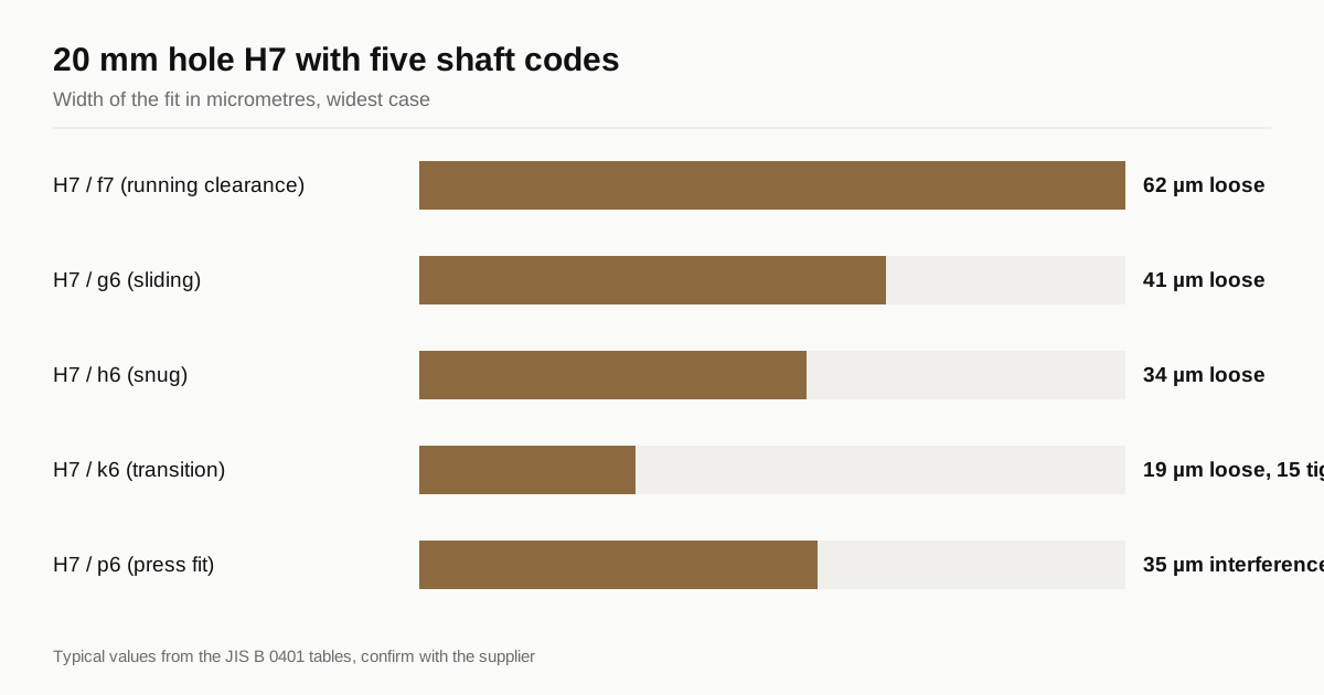
This guide shows how to decode a fit, gives the real limits for a 20 mm example and explains why stainless needs a few extra decisions.
How the code is built
A fit callout has three parts, always in the same order.
- The nominal size. The 20 in 20 H7.
- A letter. Capital for a hole, small for a shaft. It sets where the tolerance zone sits relative to the nominal size.
- A number. The international tolerance grade, IT6 or IT7 for most precision fits. A lower number is a narrower zone.
H is the one letter to remember. An H hole starts exactly at the nominal size and grows upward, so H7 on 20 mm is a hole from 20.000 to 20.021 mm. The hole never goes under size. Most drawings in this system use the hole basis, which means the hole is H and the shaft letter changes to produce the fit you want. The reason is practical. Holes are cut with fixed tools such as reamers and boring heads that are costly to change. Shafts are cut by a turning tool that can be set to any size.
For shafts, the letter tells the fit family:
- f, g, h sit on or below the nominal size and give clearance, from free running to a snug slide.
- j, k, m straddle the nominal size and give a transition: a tap with a mallet, maybe a little clearance.
- n, p, r, s sit above the nominal size and give interference, so the shaft has to be pressed or the housing heated.
The numbers for a 20 mm fit
All limits below are for the 18 to 30 mm size band, which includes 20 mm. They come from the standard tables and are given in millimetres and micrometres.
| Part | Code | Upper limit | Lower limit | Zone width |
|---|---|---|---|---|
| Hole | 20 H7 | +0.021 | 0 | 21 µm |
| Shaft | 20 f7 | -0.020 | -0.041 | 21 µm |
| Shaft | 20 g6 | -0.007 | -0.020 | 13 µm |
| Shaft | 20 h6 | 0 | -0.013 | 13 µm |
| Shaft | 20 k6 | +0.015 | +0.002 | 13 µm |
| Shaft | 20 p6 | +0.035 | +0.022 | 13 µm |
Combine the hole with each shaft and you get the actual fit:
| Pairing | Fit type | Loosest | Tightest |
|---|---|---|---|
| H7 / f7 | Clearance | 0.062 mm clearance | 0.020 mm clearance |
| H7 / g6 | Clearance | 0.041 mm clearance | 0.007 mm clearance |
| H7 / h6 | Clearance (snug) | 0.034 mm clearance | 0.000 mm clearance |
| H7 / k6 | Transition | 0.019 mm clearance | 0.015 mm interference |
| H7 / p6 | Interference | 0.001 mm interference | 0.035 mm interference |
The tightest H7 over g6 pairing leaves seven micrometres of clearance. That is enough to slide a clean part. It is not enough for a dirty one, a hot one or a rough one, which is where stainless starts to matter.
Why stainless changes the picture
Temperature. ISO and JIS fits are defined at 20 degrees C. Austenitic stainless expands at about 17 micrometres per metre per kelvin, which is much more than carbon steel. A 20 mm shaft that is 10 K above reference is about 3.4 micrometres too large. Measure it straight off the machine, warmed by the coolant and the cut, and the gauge reads wrong by half of an H7/g6 minimum clearance. Parts should be allowed to soak to room temperature before final inspection, and the inspection room should be held near 20 degrees C. Ask for that.
Work hardening and finish. A g6 shaft in stainless has a final pass of a few hundredths of a millimetre. A tool that rubs rather than cuts work hardens the surface and leaves it out of size and out of round. The practical answer is a sharp insert, a positive feed and no dwell, covered in the work hardening guide. For the hole, an H7 bore is normally finished with a reamer or a fine boring pass, not drilled to size.
Galling. This one catches buyers out. Two austenitic stainless surfaces sliding together at a seven micrometre clearance will pick up material from each other. If the drawing calls for a sliding H7/g6 pair of two SUS304 parts, raise it. A hardness difference, a different grade for one member or a surface treatment fixes it, and the choice belongs to the designer. A shop that sees only the drawing will cut what it is given.
Surface finish. A fit is a pairing of two surfaces, and roughness eats the zone. A common guide is a roughness of no more than one tenth of the tolerance. For a 13 micrometre zone that points at Ra 0.8 or finer. See the surface finish guide for how Ra and Rz are called out.
Surface treatment. Passivation removes essentially no material. Electropolishing does, by a few micrometres on each surface at least, and the amount depends on the process. A part that is to be electropolished after machining must be cut with that allowance in the size or the fit is wrong afterwards.
Three mistakes that cost a lot
Cutting to the middle of the zone and calling it done. A shop that aims at the middle of a 13 micrometre shaft zone has a margin of about six micrometres each way. With a warm part, a worn insert or a gauge that drifts, one of those margins vanishes. Shops that make fits regularly cut the first part toward the metal-in side of each zone, a small hole and a large shaft, then measure it cool and correct. A part left with material on it can still be fixed. A part cut under size cannot.
Treating the shaft basis as a typo. Some drawings, especially for bearing seats and for parts cut from ground bar, use the shaft basis, where the shaft is h and the hole letter varies. A capital letter on the shaft is not a mistake. It means a ground bar is the starting point and the hole is cut to suit.
Quoting from the code without the table. A single fit code does not give a single limit, because the same letter and number give different micrometre values in each size band. The H7 zone is 15 micrometres for 6 to 10 mm, 18 for 10 to 18 and 21 for 18 to 30. A price built on one assumed width is wrong for most diameters. The engineer reading the drawing takes the limits from the table for the actual size, and those limits go onto the order so the shop and the inspector use identical numbers.
How shops check a fit
A fit is a pair of limits, so the natural gauge is a pair of gauges. A hole is checked with a go and no-go plug gauge or a pin gauge set. A shaft is checked with a ring gauge, a snap gauge or a micrometer. For a hole, a three point bore gauge gives a reading, but a plug gauge shows both size and shape in one pass.
For parts that need a record, a CMM or an air gauge gives a number rather than a pass or a fail. If you need numbers on the inspection report, say so when you send the drawing. The seisekisho article lists what a Japanese buyer usually expects on that report.
Using the fit codes in practice
- Read the code before the size. A tolerance zone is a letter and a number, not a “tight tolerance”.
- Check the hole basis. If the shaft is the one with the capital letter, the drawing uses the shaft basis and the fit changes.
- Look at both mating parts. The fit exists between them. Quoting one part without the other misses the real requirement.
- Ask who owns the final measurement. The manufacturing shop, the inspection room or your receiving department. They need to use the same temperature and the same gauge.
- Confirm the finish and treatment order. Cut, treat and measure, or cut, measure and treat. The two orders give different sizes.
The general class from the title block still covers everything that has no code of its own. The JIS B 0405 and B 0419 guide explains what those features get. The tolerance calculator turns a size and a class into limits.
Send a drawing with fit codes to us for a quote. An engineer reads each code against the table, asks about galling and finish where the pair needs it and quotes within 24 business hours. If you order, we place the order, follow the part through machining and sign off the inspection before packing.
Questions
Is JIS B 0401 the same as ISO 286?
JIS B 0401 is the Japanese version of the ISO 286 limits and fits system. The letter and number codes and the fundamental deviations are the same, so an H7 hole or a g6 shaft means the same thing under either. Check the drawing for the edition it cites.
Does a fit callout replace the general tolerance in the title block?
Yes, for that feature. A feature with its own tolerance code or its own limits ignores the general class. Features without one still fall under JIS B 0405.
What fit is normal for a stainless pin in a stainless bore?
It depends on the job. H7 with g6 is a common sliding fit, H7 with h6 a snug location fit and H7 with p6 a press fit. For sliding pairs of the same stainless grade, a hardness or grade difference is worth discussing because identical austenitic surfaces gall.
Have a drawing for a stainless part?
Send it and an engineer reads the title block, quotes it within 24 business hours, and if you order we place, manage, inspect and ship the parts on one PO and one invoice.
Get a quoteRelated guides
SUS303Se and SUS303Cu Compared with SUS303: Which Free Cutting Grade to Use
SUS303Se and SUS303Cu against standard SUS303: what selenium and copper change for finish, cold forming and corrosion, and what a drawing should state.
SUS Spacers and Collars to JIS Drawings: What Drives the Price of Small Lots
How stainless spacers and collars are made from JIS drawings in small lots: length and parallelism, bore and set screw details, stack-up and price breaks.